I have used heat dissipation devices or heatsinks at times over most of my career.
Nothing really mysterious about them once you have the basics down.
This got started after a conversation with my friend Mike.
Mike is working on some Arduino projects but his back ground is IT and not electronic hardware. The concepts of working with heat sinks are straight forward and pretty simple.
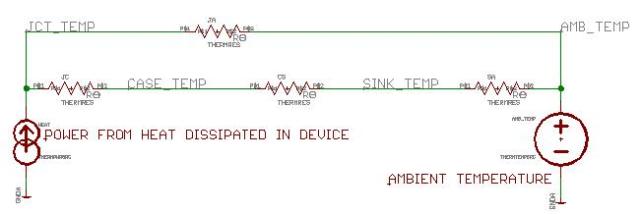
The basic idea is to treat the thermal system as a simple circuit.
The power dissipated is treated as a current source. Temperatures are treated as voltages with “ambient” temperature being treated as a voltage source. Between the power or current source and the voltage or temperature source is a series of thermal resistances, often shown as “Rtheta” or R Theta.
In the schematic above there are four thermal resistances, each is identified by the nodes it is connected to:
- Rthetaja – is the thermal resistance between the semiconductor junction and ambient temperature
- Rthetajc – is the thermal resistance between the semiconductor junction and the case or package
- Rthetacs – is the thermal resistance between the case or package and the heatsink
- Rthetajsa – is the thermal resistance between the heatsink and ambient temperature
Here is an example:
Consider a system where a 7805 regulator is used to create 5V from 12V.
The load current (current out of the 7805) is 500mA or 0.5A, well within the allowed maximum for the device.
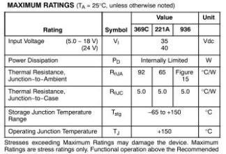
From the data sheet we get the following information:
The Package for the 7805 is a T0-220 or a 221A package in the table. The junction to ambient thermal resistance is 65 degrees C per Watt (C/W)
The power is the difference between the input voltage of 12 V and the output voltage of 5 V or 7 V, times the current of a half an amp, giving 3.5 Watts of power.
Thus the rise above ambient is 65 [C/W] * 3.5 [W] equals 227.5 degrees.
Ambient temperature is assumed to be 25 degrees Celsius (77 degrees Fahrenheit) so the resulting junction temperature would be 252.5 degrees Celsius.
The maximum allowable junction temperature is 150 degrees C (302F), so this situation is not acceptable.
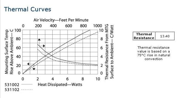
Now consider a heatsink, for example the Aavid-Thermalloy model 531002B02500G.
This heat sink is designed to be used in either still air or with a fan, also called “airflow”. From the graph the thermal resistance can be as low as 2 degrees C per Watt with a strong fan, but for this example I will use the still air value of 13.4 degrees C/W value.
The package thermal resistance between junction and case is 5 C/W, so the total is 18.4 C/W.
Multiplying the thermal resistance by the power gives a rise of 64 degrees C or a junction temperature of 89 degrees C, which is acceptable.
Now, even though the junction to ambient thermal resistance is shown in parallel with the heatsink in the schematic it is usually ignored when calculating temperature rise with a heatsink.
One thing I haven’t discussed is the thermal resistance between case and heatsink, Rthetacs. This is a necessary item and should not be overlooked. In the simplest form this is something called “thermal grease” and is, like heatsinks, available from most vendors. Thermal grease is officially called “Silicon Oil-Based Thermal Joint Compound” by one vendor, there are variations of this name among other vendors. Like lubricating grease it is a ‘paste’ consistency and often comes in a tube. It has a thermal resistance of 0.5 C/W for a TO-220. In hobby or prototype situations it works well, and tends to be messy. But it is too labor intensive for large scale manufacturing. The option is a thermally conductive, sometimes electrically insulating pad. Pads typically have thermal resistance between 0.3 and 2 C/W. And don’t forget the hardware; bolts, washers, and nuts. These are required to get the optimal thermal contact between the sink and the device.
The last part of this would be to treat this as a design challenge and show how that is done. Using the same example and most of the numbers from above the example is:
- 3.5W to dissipate,
- Maximum junction temperature 150 degrees C
- Ambient temperature 25 degrees C
- Rthetajc = 5 degrees C/W
- Rthetacs = 1 degrees C/W
The plan is that we would be loosing 6 [C/W] * 3.5 [W] or 21 degrees C between the junction and the heatsink. (The temperature is 21 degrees C above ambient or above whatever temperature is at the heatsink.)
The allowed temperature difference between 150 and 25 C is 125, less the 21 C lost between the junction and the sink. So that is 104 degrees C.
Dividing that by the power gives the maximum thermal resistance of the heatsink or 104/3.5 or 29.7 degrees C per Watt.
The chosen heatsink meets this criterion, and there are probably others. If there wasn’t a heatsink available below the calculated value we might need to add a fan or some other sort of heat removal strategy.
That is pretty much all there is to using heatsinks.


